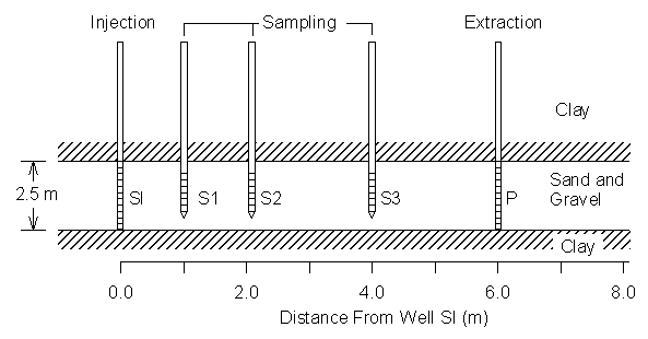
Figure 4.10.1 Schematic representation of the test zone used in biostimulation experiments.
| [TOC] | 4.10 One-Dimensional Biostimulation Experiment | [Prev. Page] | [Next Page] |
This section reproduces a modeling effort conducted by Semprini and McCarty (1991) demonstrating biostimulation of indigenous methanotrophic microbes in a saturated aquifer. The purpose of the field and modeling study was to demonstrate in-situ microbial growth due to injection of nutrients. Model simulations included advection and dispersion of two solutes: methane (the electron donor) and oxygen (electron acceptor). The model uses double Monod kinetics to represent biomass growth and nutrient uptake. A single Monod relationship using oxygen as the limiting substrate represents biomass decay.
Figure 4.10.1 illustrates the field experiment design.
Figure 4.10.1 Schematic representation of the test zone used in
biostimulation experiments.
The aquifer was located at a depth of 6.0 m and consisted of fine to course-grained sand. The upper confining layer consisted of clayey sand while the underlying layer consisted of greenish-gray silty clay (Roberts et al., 1990). The experimental well field was designed to inject nutrients into the aquifer at well SI and extract all the injected fluid at well P. Monitoring wells S1, S2 and S3 were located 1.0, 2.2 and 4.0 m from the well SI.
The most difficult part of modeling this experiment is correctly representing boundary conditions. For the purpose of limiting well head clogging, the field study used alternating pulsing of electron donor and acceptor at the injection well. This requires the use of alternating step functions to represent injection concentrations in the model.
Table 4.10.1 presents the input parameters used in this study. The input parameters are identical to those used in the literature except the duration of the first pulsing scheme is shorter by 0.3 of a day.
Table 4.10.1 One-Dimensional Biostimulation Parameters
| Parameter Description | Notation | Value |
|---|---|---|
| Aquifer Length (m) | 24 | |
| Number of Nodes | 25 | |
| Grid Spacing (m) | D x | 0.1 |
| Pore Water Velocity (m/d) | v | 2.9 |
| Oxygen Dispersion (m2/d) | DSA | 0.25 |
| Methane Dispersion (m2/d) | DSD | 0.25 |
| Max. Substrate Cons. Rate (g/gÀd) | k | 1.2 |
| Methane Half Saturation (mg/l) | KSD | 2.0 |
| Oxygen Half Saturation (mg/l) | KSA | 1.0 |
| Yield Coefficient (mg/mg) | Y | 0.5 |
| Cell Decay Coefficient (d-1) | b | 0.15 |
| Stoichiometric Ratio (mg/mg) | F | 2.4 |
| Biodegradable Cell Fraction | fd | 0.8 |
| Cell Decay O2 Demand (mg/mg) | dc | 1.42 |
| Initial Biomass Conc. (mg/l) | Xi | 0.18 |
| Oxygen Inject. Conc. (mg/l) | CAo | 26.3 |
| Methane Inject. Conc. (mg/l) | CDo | 16.5 |
| O2 Pulse Interval (d) for (0-18.8d) | ta | 0.02 |
| O2 Pulse Interval (d) for (18.8-25d) | ta | 0.34 |
| CH4 Pulse Interval (d) for (0-18.8d) | td | 0.01 |
| CH4 Pulse Interval (d) for (18.8-25d) | td | 0.17 |
The following figures illustrate the results from this numerical model compared to modeled and field values from Semprini et al. (1991).
Figure 4.10.2 illustrates breakthrough curves for oxygen and methane 2.2 m downstream from the injection point for the first 400 hours of the experiment.
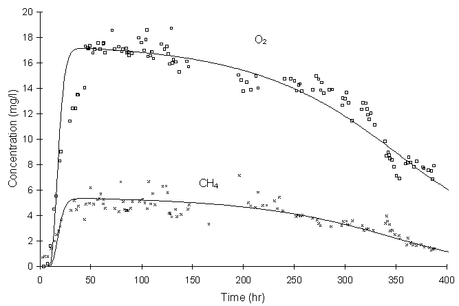
Figure 4.10.2 Experimental (symbols) and modeled (lines, this model)
breakthrough curves of methane and oxygen
at observation well S2, 2.2 m from injection well SI, (Figure 4 in literature).
Figure 4.10.2 shows that model simulations predict smooth concentration curves while the actual data more prominently show the effects of the nutrient pulsing scheme. Also, Figure 4.10.2 shows that nutrient consumption by biomass growth and decay becomes significant as the experiment proceeds in time. This is due to excessive biomass growth illustrated in Figure 4.10.3.
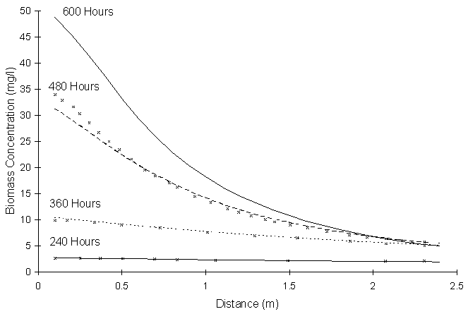
Figure 4.10.3 Modeled biomass profiles computed by Semprini and McCarty
(symbols) and this model (lines), (Figure 5 in literature).
Figure 4.10.3 illustrates theoretical biomass concentration profiles for various snapshots in time. The symbols represent data presented by Semprini et al., lines represent values computed by this model. No experimental values were available, obtaining them would have disturbed the subsurface.
Figure 4.10.3 shows that theoretical biomass concentrations continuously grew throughout the entire length of the simulation, especially close to the injection well. One of the points of the alternating pulsing scheme was to eliminate this problem. The results suggest that alternating nutrient pulsing, as implemented in this experiment, was not successful in preventing excessive biomass growth close to the injection well.
Figure 4.10.4 illustrates breakthrough curves for oxygen and methane 2.2 m downstream from the injection point for the last 200 hours of the experiment. Symbols and lines represent experimental and numerical values, respectively.
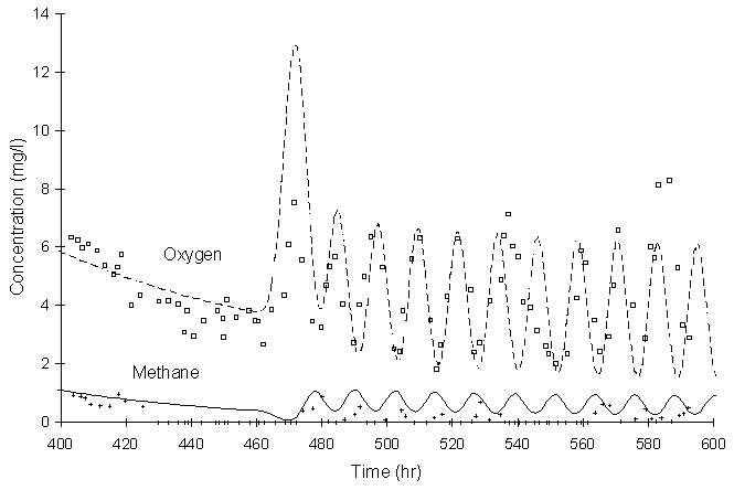
Figure 4.10.4 Experimental (symbols) and modeled (lines, this model)
breakthrough curves of methane and oxygen
at observation at well S2 under alternative pulsing strategy (Figure 7 in literature).
Figure 4.10.4 shows that model simulation and experimental results agree well, but it appears that the model overpredicts methane concentrations. There may be another process in the aquifer acting as a methane sink that the model does not represent.
Figure 4.10.5 illustrates theoretical biomass concentrations at a point 2.2 m downstream from the injection wells. Symbols and lines represent values reported by Semprini et al. and this study, respectively.
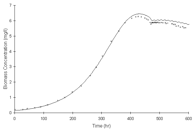
Figure 4.10.5 Modeled biomass concentrations computed by Semprini and
McCarty (symbols)
and this model (lines) at well S2 (Figure 8 in literature).
There appears to be a small difference between the values reported by Semprini and McCarty and those calculated by this model. One of the potential reasons could be error caused by digitizing of the data from the literature. The trends still appear to be the same.
This section has shown that the model can simulate a real-world in-situ bioremediation scenario. The above figures show that the model appears capable of reproducing the modeling effort conducted by Semprini and McCarty. The modeled and experimental values in figures Figure 4.10.2 and Figure 4.10.4 matched. The predicted biomass concentrations from this model and the literature agreed as well.
| [Home] | [Table of Contents] | [Prev. Page] | [Next Page] |
| A Two Dimensional Numerical Model for Simulating the
Movement and Biodegradation of Contaminants in a Saturated Aquifer ® Copyright 1996, Jason E. Fabritz. All Rights Reserved. |
|||